Two-Pressure Operating “Valve”
Specializing in standard and custom high pressure valves for
water hydraulics and other high pressure water systems.
TWO-PRESSURE VALVE ASSEMBLY
FOR WATER, 95/5 OR OIL SERVICE

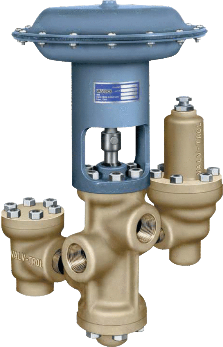
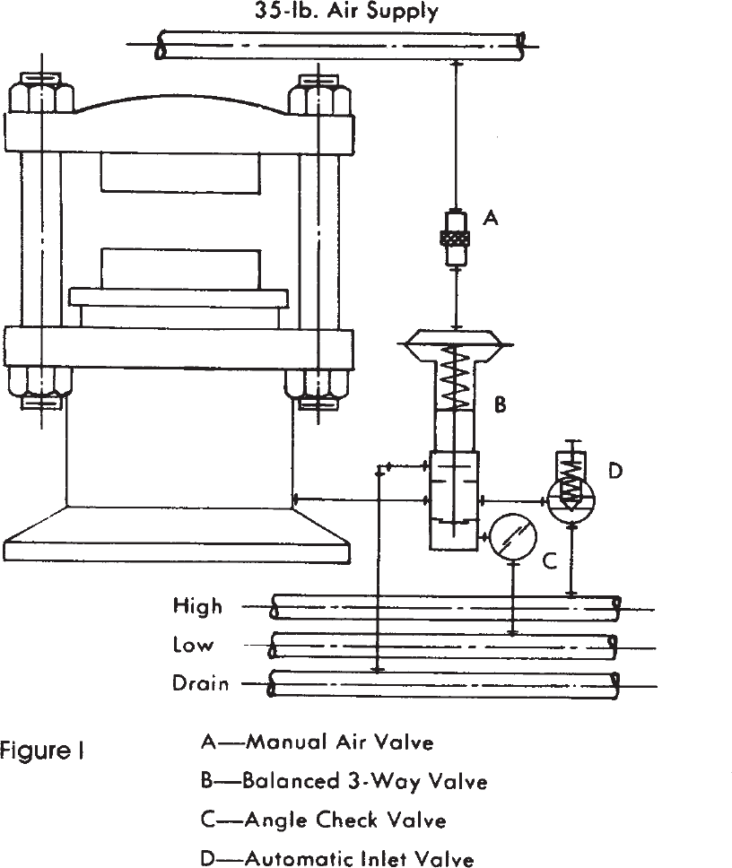
The Valv-Trol Two-Pressure Operating “Valve” is actually anassembly
of three of our standard valves. This “valve” has proven to be an efficient and
economical way to actuate a single acting hydraulic press or cylinder. The use
of a low pressure fluid for most of the stroke conserves high pressure fluid
which is more costly to generate. When the ram meets resistance near the
end of its stroke,the higher pressure fluid can be applied automatically for
final squeezing or clamping.
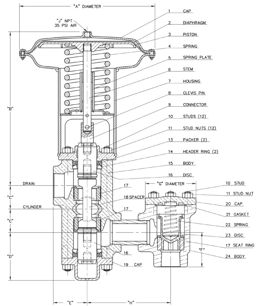
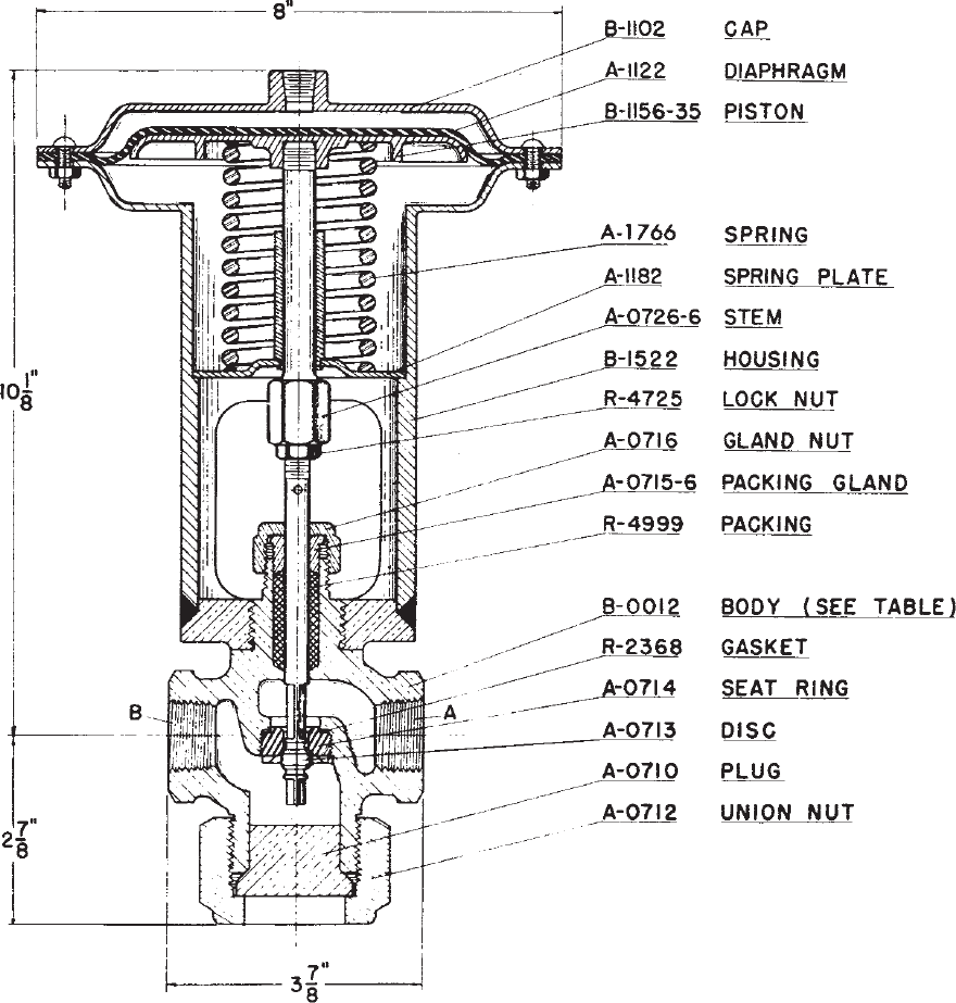
Each assembly is made up of a Balanced 3-Way Valve, an Angle Check Valve,
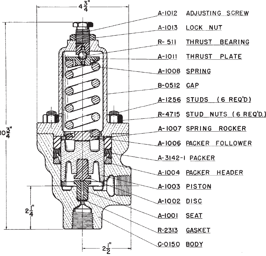
and a High Pressure Inlet Valve. Our popular model B-0511 automatic inlet
valve is standard with all sizes. It can be adjusted to open when ram pressure builds up to any point between 150 and 400 PSI (10 and 28 Bar). Optional to
automatic valves are shown on Bulletin A-7. Our model C-0008, 2-way
Normally Closed Diaphragm Valve is often used if separate control is
more desirable than automatic operation
Each valve is an independent unit
Can be mounted in the most convenient position for simplified piping.
Maintenance is simplified.
Can be mounted in the most convenient position for simplified piping.
Port Sizes | Construction * | ||||||||
---|---|---|---|---|---|---|---|---|---|
Model | Basic Size | Max.PSI * | Low Press | High Press. | Cyl. & Drain | Cv | Body | Replaceable Trim | Seals |
D-1050 | 3/4" | 3500 (240 Bar) | 1/2" or 3/4" NPT | 3/4" NPT | 3/4" | 3.5 & 4.9 | Bronze | Hardened S.S. | Buna N |
D-1051 | 1" | 3500 (240 Bar) | 3/4" or 1" NPT | 3/4" NPT | 1" | 9.0 & 13.0 | Bronze | Hardened S.S. | Buna N |
D-1052 | 1-1/4" | 3500 (240 Bar) | 1" or 1-1/4" NPT | 3/4" NPT | 1-1/4" | 1-1/4" | Bronze | Hardened S.S. | Buna N |
D-1053 | 1-1/2" | 3500 (240 Bar) | 1-1/4" or 1-1/2" NPT | 3/4" NPT | 1-1/2" | 19.2 & 30.0 | Bronze | Hardened S.S. | Buna N |
D-1054 | 2" | 3500 (240 Bar) | 1-1/2" or 2" NPT | 3/4" NPT | 2" | 20.0 & 40.0 | Bronze | Hardened S.S. | Buna N |
D-1055 | 3" | 3500 (240 Bar) | 2-1/2" or 3" NPT | 3/4" NPT | 3" | 54.6 & 83.5 | Bronze | Hardened S.S | Buna N |
D-1056 | 4" | 3500 (240 Bar) | 3" or 4" NPT or Flanged | 3/4" NPT | 4" | 88.0 & 140.0 | Stee | Hardened S.S. | Buna N |
*Consult factory for special requirements.When ordering, specify model no., port
sizes, your system pressures, and the H.P. inlet valve required.
The Valv-Trol Advantage .
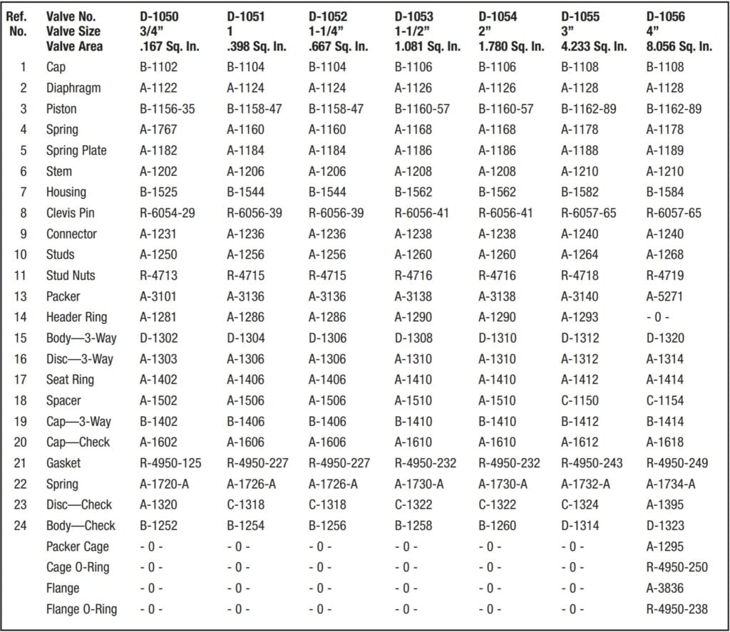
Many parts of Valv-Trol Valves are interchangeable between the same size 2-way, 3-way, and check valves. This helps you to reduce your spare parts inventory and allows us to maintain a more complete inventory for your emergency availability and shorter lead times
Our valves are all subjected to 100% pressure testing to ensure a drop
tight seal before we ship to our customers.
TWO-PRESSURE VALVE ASSEMBLY
BULLETIN A-1E part 2

On 3” check valves, install cone spring with small end in the disc.
VALVE NUMBER | PIPE SIZE | A | B | C | D | E | F | G | H | J |
---|---|---|---|---|---|---|---|---|---|---|
D-1050 | 3/4” | 8” | 7-3/4” | 1” | 2-3/8” | 2-1/8” | 2-1/4” | 3” | 2-1/4” | 1/4” |
D-1051 | 1” | 11” | 13-1/4” | 1-3/4” | 4” | 2-3/4” | 2-1/2” | 4” | 2-1/2” | 1/4” |
D-1052 | 1-1/4” | 11” | 13-1/4” | 1-3/4” | 4” | 2-3/4” | 2-5/8” | 4” | 2-3/4” | 1/4” |
D-1053 | 1-1/2” | 13” | 14-7/8” | 2-1/4” | 4-5/8” | 3-1/8” | 3” | 4-7/8” | 3” | 1/4" |
D-1054 | 2” | 13” | 14-7/8” | Table Data | 4-5/8” | 3-1/4” | 3-1/4” | 4-7/8” | 3-1/4” | 1/4” |
D-1055 | 3” | 20” | 21-1/2” | 3-1/4” | 6” | 4-1/2” | 4-3/4” | 7” | 4-3/4” | 1/2” |
D-1056 | 4” | 20” | 21-3/4” | 4” | 7-5/8” | 8-3/8” | 6-3/4” | 9” | 8-3/8” | 1/2” |
Illustration typical of 3/4”-3” valves. 4” 3-way ports, and check valve side port are furnished with weld neck companion flanges.
TWO-PRESSURE OPERATING VALVE
LOW 50-2000 PSI (3-138 Bar) HIGH TO 3,500 PSI (240 Bar)
parts list
Ref. No. | Valve No. Valve Size Valve Area | D-1050 3/4” .167 Sq. In. | D-1051 1 .398 Sq. In. | D-1052 1-1/4” .667 Sq. In. | D-1053 1-1/2” 1.081 Sq. In. | D-1054 2” 1.780 Sq. In. | D-1055 3” 4.233 Sq. In. | D-1056 4” 8.056 Sq. In. |
---|---|---|---|---|---|---|---|---|
1 | Cap | B-1102 | B-1104 | B-1104 | B-1106 | B-1106 | B-1108 | B-1108 |
2 | Diaphragm | A-1122 | A-1124 | A-1124 | A-1126 | A-1126 | A-1128 | A-1128 |
3 | Piston | B-1156-35 | B-1158-47 | B-1158-47 | B-1160-57 | B-1160-57 | B-1162-89 | B-1162-89 |
4 | Spring | A-1767 | A-1160 | A-1160 | A-1168 | A-1168 | A-1178 | A-1178 |
5 | Spring Plate | A-1182 | A-1184 | A-1184 | A-1186 | A-1186 | A-1188 | A-1189 |
6 | Stem | A-1202 | A-1206 | A-1206 | A-1208 | A-1208 | A-1210 | A-1210 |
7 | Housing | B-1525 | B-1544 | B-1544 | B-1562 | B-1562 | B-1582 | B-1584 |
8 | Clevis Pin | R-6054-29 | R-6056-39 | R-6056-39 | R-6056-41 | R-6056-41 | R-6057-65 | R-6057-65 |
9 | Connector | A-1231 | A-1236 | A-1236 | A-1238 | A-1238 | A-1240 | A-1240 |
10 | Studs | A-1250 | A-1256 | A-1256 | A-1260 | A-1260 | A-1264 | A-1268 |
11 | Stud Nuts | R-4713 | R-4715 | R-4715 | R-4716 | R-4716 | R-4718 | R-4719 |
12 | Packer | A-3101 | A-3136 | A-3136 | A-3138 | A-3138 | A-3140 | A-5271 |
13 | Header Ring | A-1281 | A-1286 | A-1286 | A-1290 | A-1290 | A-1293 | - 0 - |
14 | Body—3-Way | D-1302 | D-1304 | D-1306 | D-1308 | D-1310 | D-1312 | D-1320 |
15 | Disc—3-Way | A-1303 | A-1306 | A-1306 | A-1310 | A-1310 | A-1312 | A-1314 |
16 | Seat Ring | A-1402 | A-1406 | A-1406 | A-1410 | A-1410 | A-1412 | A-1414 |
17 | Spacer | A-1502 | A-1506 | A-1506 | A-1510 | A-1510 | C-1150 | C-1154 |
18 | Cap—3-Way | B-1402 | B-1406 | B-1406 | B-1410 | B-1410 | B-1412 | B-1414 |
19 | Cap—Check | A-1602 | A-1606 | A-1606 | A-1610 | A-1610 | A-1612 | A-1618 |
20 | Gasket | R-4950-125 | R-4950-227 | R-4950-227 | R-4950-232 | R-4950-232 | R-4950-243 | R-4950-249 |
21 | Spring | A-1720-A | A-1726-A | A-1726-A | A-1730-A | A-1730-A | A-1732-A | A-1734-A |
22 | Disc—Check | A-1320 | C-1318 | C-1318 | C-1322 | C-1322 | C-1324 | A-1395 |
23 | Body—Check | B-1252 | B-1254 | B-1256 | B-1258 | B-1260 | D-1314 | D-1323 |
  | Packer Cage | Table Data | - 0 - | - 0 - | - 0 - | - 0 - | - 0 - | A-1295 |
Cage O-Ring | - 0 - | - 0 - | - 0 - | - 0 - | - 0 - | - 0 - | R-4950-250 | |
Flange | - 0 - | - 0 - | - 0 - | - 0 - | - 0 - | - 0 - | A-3836 | |
Flange O-Ring | - 0 - | - 0 - | - 0 - | - 0 - | - 0 - | - 0 - | R-4950-238 |
THE VALV-TROL CO., STOW, OHIO
TWO-PRESSURE OPERATING VALVE
BULLETIN A-1 part 4

VT AUTOMATIC HIGH PRESSURE INLET VALVE NO. B-0511
PARTS DRAWING
FOR LOW PRESSURES 150 TO 400 PSI. (10 to 28 Bar) SEE BULLETIN A-7 FOR MODELS WITH OTHER LOW PRESSURE RATINGS
VT DIAPHRAGM CONTROLLED HIGH PRESSURE INLET VALVE NO. C-0008
PARTS DRAWING
FOR Control PESSURES 150 TO 400 PSI. (10 to 28 Bar) SEE BULLETIN A-7 FOR MODELS WITH OTHER Control PRESSURE RATINGS


TWO TYPICAL HYDRAULIC PRESS CIRCUITS
Figure 1 shows one of the simplest ways to control a press or cylinder with our valves. With this valve arrangement on a two-pressure hydraulic system, the cycle is started by applying air pressure to the diaphragm of valve “B”. This can be done with a 3-way air valve that is manually or solenoid operated. Low pressure fluid can now enter the check valve “C” and the 3-way valve “B”. When the ram or piston meets resistance at the end of its stroke, the pressure builds until the automatic high pressure inlet or sequence valve “D” opens the high pressure port. Now the ram has the maximum amount of squeeze. Valve “C” prevents loss of high pressure back into the low pressure system. The ram can be bumped as many times as required by shifting the air valve “A
When the ram is ready to be retracted, the air supply is removed from valve “B” and the fluid is drained back to the reservoir. When the pressure to the ram has bled down to the setting of valve “D” the high pressure port closes.
Figure II shows a more complete way of controlling a hydraulic press.in addition to the basic opening and closing of the ram, it allows slow opening or closing of the press, stopping of the ram at any point in its stroke, delaying of high pressure kick-in, and operation of pullback and knock-out cylinders at the proper times. A pressure reducing valve (Bulletin A-31) is used to control the tonnage of the press. In this circuit, a Valv-Trol time cycle controller is used to completely control the sequence and timing functions of the solenoid valves.
There are many ways to valve and control a press. Let our years of experience help you meet your exact requirements

